


Ben Lipscomb, P.E., Engineering manager, National Comfort Institute, Inc. (NCI)
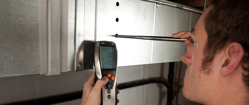
Airflow rate through HVAC equipment can be one of the most difficult measurements to make in the field. This is mostly due to common equipment and system configurations that do not provide acceptable measurement sites. Ideally, we’d measure average air velocity through a straight section of duct near the equipment. We’d measure using a manometer and pitot tube or a thermal anemometer. Then we’d multiply average velocity by duct cross-sectional area to find volumetric flow rate. This method can achieve accuracy on the order of ?4 or 5% under ideal conditions. However, it’s rare to have the luxury of performing a textbook traverse in the field.
Direct Measurement
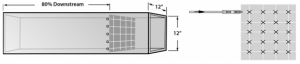
Directly measuring air velocity through the equipment requires a length of straight duct before and after the measurement plane for best accuracy. Once you’ve selected the measurement plane, perform a traverse, making multiple measurements at various points within that plane. The number and location of points necessary for an accurate average velocity depends on the shape and size of the duct.
ASHRAE 111 provides guidance on selection of an acceptable measurement plane, as well as selection of traverse points using either the Log-Tchebycheff or Equal Area methodology. Of these two methodologies, multiple studies suggest that Log-Tchebycheff is more accurate. However, it’s easier to calculate the traverse point locations using the equal area method, and the accuracy is acceptable for most HVAC applications.
Non-Ideal Measurement Locations
When an ideal traverse plane isn’t available, ASHRAE 111 also provides guidance for determining whether a traverse produces an accurate result based on measurement values. The guidance basically states that 75% of the velocity measurements in the traverse need to be greater than 10% of the maximum velocity measured, and none of the measurements can be negative. If we must take a measurement in a questionable place in the duct system, this guidance can be a valuable tool to boost confidence in our result.
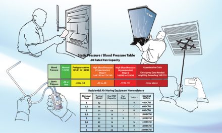
Plotting CFM using Static Pressure and RPM
When you can’t achieve direct air velocity measurements because of the system configuration, we recommend estimating airflow using a manufacturer-supplied fan curve or fan performance table. In this approach,measure the fan speed in rotations per minute (RPM) and fan static pressure rise. Larger fans typically come with built-up air handlers. A full fan curve is usually available for the fan itself.
With packaged equipment, fan data is most often provided in the form of a table. Packaged equipment usually provides the data in relation to Total External Static Pressure (TESP) instead of fan static pressure rise. The TESP is the pressure rise from the return air inlet to the supply air outlet of the equipment. Fan static pressure rise is from the inlet to the outlet of the fan alone.
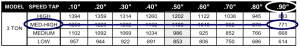
For direct-drive motors common on residential equipment, the manufacturer usually provides airflow data in relation to static pressure and the motor speed setting (i.e. ‘speed tap’ or ‘dip switch setting?). In these cases, the RPM measurement is not necessary.
Manufacturer-Specific Nuances
Manufacturers have various approaches for developing performance tables. When applying the data to field measurement, pay special attention to the conditions used to develop the table. For example, one manufacturer could develop their table for a ‘dry’ coil with no filter. Meanwhile, another manufacturer develops one for a ‘wet’ coil with a ‘clean’ filter. Accessories or optional equipment — like gas heat exchangers, electric heat strips, and economizers — also typically requires special consideration.
One way to deal with these nuances is to determine differences between the internal pressure drops of installed equipment and the equipment configuration used to develop fan performance data. Add or subtract internal pressure differences from measured TESP. Then use the resulting adjusted TESP and measured RPM to determine airflow.
 Brake Horsepower Plotting
Some manufacturers provide airflow data in relation to static pressure and brake horsepower (BHP) instead of, or in addition to, RPM. In these cases, use a power meter to measure input power to the motor. Next, estimate motor and drive (e.g. v-belt drive) efficiency to determine BHP. It is important to remember that motor efficiency is not static, but varies with motor loading. Depending on their size, motors usually achieve near-rated efficiency between 70% and 100% of their rated load. Below 70% loading, efficiency begins to drop off.
When both RPM and BHP data is provided , you can use both, plus the static pressure rise, to verify your measurement. They will also establish a range if the two methods produce different results.
 Fan Condition
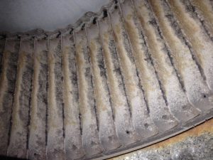
Equipment manufacturer data is developed with clean fans that are in good condition. Bent, broken, or dirty fan blades and housings impact fan performance and are not accounted for in manufacturer data. There’s no consistent way to determine the impact of fan condition. However, it’s important to remember that a dirty or damaged fan could produce airflow 10% to 20% lower than indicated by manufacturer data for a given pressure and RPM.
Assessing airflow through HVAC equipment in the field can be difficult. But it is critical for achieving capacity and efficiency at or near manufacturer ratings. It is also a pre-requisite for properly charging refrigerant circuits and performing other refrigerant temperature and pressure-based diagnostics. Poor airflow through the equipment can indicate issues like dirty filters, a clogged coil, or a worn belt. It can also be symptomatic of undersized or otherwise restricted ducts. Take the time to measure and assess airflow. Doing so unlocks a range of diagnostic techniques that find problems often invisible to other diagnostic methods. This helps avoid misdiagnoses that can occur when refrigerant is checked before airflow is verified.
Ben Lipscomb, P.E. is the engineering manager for National Comfort Institute, Inc. (NCI). He is a registered Professional Engineer with personnel and project management experience, specializing in commercial and residential HVAC energy efficiency. His experience ranges from energy efficiency program design and implementation, to policy and regulatory consultation. Lipscomb also works in measurement and verification consultation, laboratory and field research, application of codes and standards, and HVAC system Design/Build projects.


Excellent article and great information, Ben
Thank you