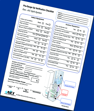
Indeed, the main goal at this stage is to make sure you won’t alter airflow after adjusting the refrigerant charge. Why do this? Because, airflow impacts the refrigerant circuit’s operation. If you answer yes to all these items on the checklist and see external indications that there is a refrigerant charge issue, you can continue to gauge up.
Proper Manifold Use Techniques

To access the refrigerant side of the system, you need a quality refrigerant manifold and hoses. For best accuracy, NCI recommends using digital manifolds that can measure temperatures in addition to pressure. Pressure resolution should be 0.1 psi, and temperature resolution should be 0.1? F.
In addition, NCI recommends using hoses with low-loss fittings and/or ball valves to minimize refrigerant loss and contamination. Real-time calculations of superheat and subcooling remove human error performing the math.
NCI also recommends a calibration period of 24 months, with periodic gauge accuracy verification against virgin tanks of refrigerant.
Purge in virgin refrigerant through the gauges into your hoses before attaching the manifold to your customer’s system.
This purge minimizes introducing atmospheric gas and moisture into the customer’s system.
Next, attach hoses to the system. Allow the system to run for 15 minutes before adjusting the refrigerant charge.
If the indoor temperature is too low to allow for 15 minutes of run time, turn up the heat and turn on the hot water in a shower to add latent heat.

Data Collection: Superheat
Once your system is stable, begin collecting data and diagnosing the refrigerant circuit operation. Systems with fixed orifice pistons or capillary tubing will rely primarily on the superheat charging method.
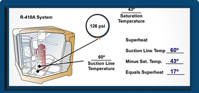
You calculate Superheat by directly measuring the suction line temperature and subtracting the saturation temperature correlated with the suction line pressure.
Superheat is an important indicator for problems within the refrigerant circuit. Low superheat can lead to liquid entering the compressor causing valves to fail or the oil to be washed out of the compressor.
Low superheat can also show when a system is overcharged or a Thermal Expansion Valve (TXV) is overfeeding. See the table below for target superheat depending on the metering device in the system.
Data Collection: Subcooling
Subcooling is the amount of heat rejected from the refrigerant into the outdoor airflow beyond the refrigerant’s saturation temperature in the condenser. To calculate subcooling, measure and convert your liquid line saturation temperature, then subtract the liquid line temperature.
Click Below for the Next page:


Recent Comments