


Measured Component Pressure Drops Can Show:
- Restrictive air filters – The solution is to change the filter to a “V” configuration. This increase’s surface area by using two filters instead of one
- Less restrictive coils
- Performance grade registers and grilles.
Combustion Appliance Zone (CAZ)
In every home or building where gas-fired appliances are used, there is a flue pipe venting outside. Several issues can cause combustion issues leading to CO production in those spaces. We call those spaces the combustion appliance zone or CAZ.
It is imperative to measure the pressure of the CAZ with reference to an adjoining room to see if the CAZ pressure is operating at a safe level. Be sure there is no interference from exhaust fans and return duct leakage.
Some solutions to potential issues include:
- Duct Sealing
- Pressurize CAZ.
Airflow Temperature Diagnostics
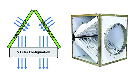
RIGHT: Photo of the AirScape SFB-V Series MERV-13 V-Bank Inline Filter Box.
Every HVAC company should measure equipment temperature change (∆T). How many companies require technicians to measure system ∆T?
System ∆T is not the same as equipment ∆T. For example, let’s say you have an HVAC system in the attic, and it’s a hot summer day with 87° ambient and 120° attic air. The system is pulling 15% of the return air from the attic. This situation is likely one reason the equipment’s ∆T is only in the mid-teen range. It will take longer for the system to satisfy the thermostat.
Two repair opportunities include:
- Duct sealing. Always verify static pressure whenever sealing ducts. You may solve one issue and cause a more severe one
- Add duct insulation.
BTU Measurements:
Verify airflow by any of the following methods:

- Duct traverse. Add airflow from all supply air registers using a high-quality air-balancing hood
- Use manufacturer fan charts
- Measure and record dry bulb and wet bulb temperatures. Then you can determine BTU per hour (BTUH).
Here’s what you need when using a manufacturer fan chart:
- Inspect the blower wheel for cleanliness (clean if dirty)
- Measure TESP
- Verify fan speed on direct drive motors, and measure RPM belt/pulley fan
- Plot fan CFM from the manufacturer’s fan charts
- Measure dry-bulb temperature
- Measure wet-bulb temperature
- Convert wet-bulb readings into enthalpy, subtract supply air enthalpy from return air enthalpy to determine enthalpy change (∆H)
Formula:
- CFM x ∆T x 1.08=SBTU/Hour (sensible BTUH)
- CFM x ∆H x 4.5=TBTU/Hour (Total BTUH)
- TBTU/Hour minus SBTU/Hour equals Latent BTU/Hour (LBTUH).
Click Below for the Next Page:


Recent Comments