


Then you need to take four pressure readings to diagnose any HVAC system properly:
- Total external static pressure
- Filter pressure drop (∆p)
- Coil pressure drop (∆p)
- Supply and return duct pressures.
Before obtaining these measurements, do a visual inspection of the blower wheel to make sure it is clean and rotates properly. If all is well, then make sure the fan speed settings are correct for the type of fan installed. And finally, it’s time to plot the system fan airflow.
Plot Fan Airflow
Another part of mastering airflow diagnostics is knowing the fan airflow. Fan airflow points you in the right direction to correct excessive TESP. You might have too much or not enough airflow depending on system needs. The solution to each problem is different.
To plot this, you need a fan table. Most manufacturers provide fan tables in the installation instructions or on the blower door. You can also do a web search for the brand and model number of the fan to find the right table.
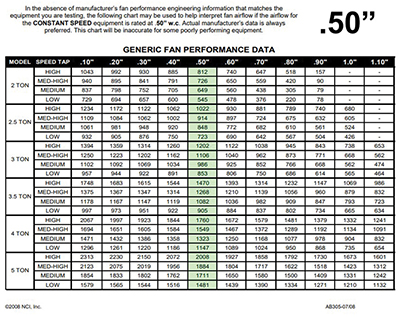
Don’t spend too much time searching. National Comfort Institute (NCI) has developed generic tables that will work (See Figure 2). For more info on NCI’s fan table, go to ncilink.com/SP-FanG You plot fan airflow using the operating fan speed and the measured TESP.
If you have the manufacturer’s table, locate the air-handling equipment’s model number, then locate the fan speed in use and lightly circle it. Next, find the column closest to your measured total external static pressure and lightly circle it. You should have two points circled on the fan table at this point.
Line up your measured total external static pressure and the fan speed being used. The point where they intersect is the airflow amount the fan is moving. Record this reading to diagnose the system and compare it to your required airflow.
This process may seem like a lot of testing steps, but it’s more intimidating on paper than it is to do the test. You can measure static pressure and plot fan airflow in less than five minutes with a bit of practice.
Duct Traverses
Sometimes it may be necessary to do a duct traverse when plotting fan airflow is questionable. This test offers a very accurate means for determining airflow and has been used by air balancers for decades. It is the gold standard mastering airflow measurement in commercial and residential HVAC systems for many.
A traverse is a series of measurements to determine the average velocity or airspeed moving through an opening. Air velocity is measured in a grid pattern through a variety of openings. These openings typically include ducts, registers, grilles, filters, economizers, and grease filters.
Average air velocity, by itself, doesn’t provide a lot of information about ducts or the mechanical system. But once you combine it with a simple formula, you can determine airflow.
The formula is Area x Velocity = CFM. This formula uses the following components.
- Area = the inside dimensions of the duct measured in square feet
- Velocity = the average speed of air, measured in feet per minute (FPM) through the duct
- CFM = the calculated airflow moving through the duct. Also known as cubic feet per minute.
So, once you determine the average velocity reading, multiply that by the inside area of the duct, and you have the calculated airflow. The good news: you don’t have to do the math. Thanks to the advances in test instruments today, they perform the math as you measure.
For more information on the right tools needed to do a duct traverse, see ncilink.com/TraverseTools.
Click Below for the Next Page:


Recent Comments