


Preliminary Hydronic Testing & Balancing
After receiving the approved TAB Pre-Submittal, we can note any clarifications from the design team and proceed with pre-testing the main pumps.
First, we coordinate with the Temperature Control Contractor so they can make a “global command” on the DDC (direct digital control) network to toggle all the hydronic heating control valves to the fully open position.
This allows us to measure the pump’s operating DP with all valves open to determine the required flow rate (GPM). This process is commonly known as a “full call” for heating and cooling.
We record all the motor data and specifications on the pump rail tag in the field. Some of this information may vary slightly from the equipment submittals. We typically verify low-load amperage specifications for the motor in the field.
Note: Before beginning the pre-TAB work on a hydronic system, verify the system piping is fully installed, that all mains and isolation valves are in the open position, that all control valves are toggled open, and that all the air is purged from the system.
If this is a multistory building, you must calculate a minimum primary pump suction pressure so that the upper levels do not operate with a negative suction pressure.
Operating a hydronic system in a negative pressure risks drawing in air. If automatic air bleed devices are installed in the system, they not only bleed unwanted air from the system but can also allow air into it. Ensure the system is filled properly to prevent operating at a negative suction pressure.
Primary Pump Preliminary Testing
When water balancing a hydronic system, start by testing the primary pumps. Begin by confirming whether one pump or two pumps are designed to operate.
Typically, dual pumps are for redundant backup. If a single gauge is installed to measure pump DP, we will use the bridge gauge installed at each pump. Should that gauge have too low of a pressure range and/or we think it is unreliable, we will temporarily install our own gauge to take the DP readings.
Note: Only install one gauge with ball valves to take all the pump measurements. Gauges are like snowflakes. No two are alike. For every one psi of incorrect reading, that dictates 2.3-in. of incorrect head DP.
Also, note that bridge gauges must be installed at each pump flange on the supply and return connections. A common mistake is to find the suction bridge gauge connection at the inlet of the suction strainer. This situation can add unwanted pressure drop and thus provide an unreliable reading.
A Common Error
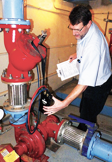
Another common error is that we find a bridge gauge was either not specified and/or not installed. When we run into that situation, we shut the pump off, then isolate it from the system by closing the shut-off valves on the suction and discharge sides of the pump.We then remove the plugs at the flanges and install a Pete’s Plug fitting at each side of the pump. We can test the pump with our digital hydronic manometer by inserting the test needles into the Pete’s Plug fittings.
Next, we perform a “Deadhead no-flow” test on each pump. We start by measuring the pump differential at “NO FLOW” by closing off the pump’s discharge valve. Doing this lets us verify the pump impeller size on the manufacturer’s pump curve.
Should the deadhead reading be slightly different than what the manufacturer’s pump curve indicates at no flow, we plot a new pump curve next to the original one and use that curve to verify the total pump flow.
Read the rest of this article on our website at ncilink.com/KHeikkila4
Click Below for the Next Page


Recent Comments