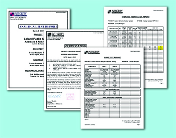
We then start to mark up our hydronic drawings and number each load starting with the first heating load from the supply heating main to the last load on the system. We number each hydronic load in our Hydronic Test Report.
After tallying the entire hydronic system, we fill in each load’s specified flow rate. It may get confusing with discrepancies between the flow rates listed on the mechanical schedule and those recorded in the approved equipment submittal.
If the two flow rates differ, we list the specified flow rate from the approved equipment submittals. We add a note to that hydronic load indicating which flow rate we used for clarification.
This is common when engineers specify mechanical equipment based on a particular manufacturer. When other manufacturers bid on the equipment, flow rates may differ based on providing the same required heating or cooling Btus.
Review Equipment Submittals
Always review equipment submittals to verify the required flow rate (GPM). Now add up all the hydronic loads and the listed required flow rates to determine your “connected load.”

and Balancing. Courtesy of Kevin Heikkila
A pump size is typically based on the required flow rate and calculated operating DP. The design pump flow rate and the “connected load” are usually nearly equal on most hydronic systems. If the pump design flow rate is less than the connected load, verify if this system is based on a diversity factor. If that is not the design intent, there is a good chance that the pump will still be able to provide the flow rate for the connected load.
Another possibility is that the design team did not confirm the connected load before selecting the pumps. You may have to increase the pump size and flow rate.
You’ll need balance valves for each hydronic load. The mechanical detail pages should illustrate such. Should you find any balance valves missing on a hydronic detail, say so in the TAB Submittal. More on that below.
Testing, Adjusting, Balancing Submittal
Most TAB specifications require you to send a “TAB Plan” submittal to the design team for review and approval before commencing work. This submittal is your opportunity to flush out any questions or concerns.
We start by being upfront with our understanding of the specified TAB work. Being upfront means listing all the systems and equipment we plan to test and balance on the inside page of our TAB submittal. Should we be missing anything, the design team can note that correction when they review and return our submittal.
We also list in our TAB submittal any issues that would prevent us from properly testing and balancing the hydronic system. What am I talking about? Here is a list of some problems we commonly identify.
- No balance device is illustrated on the hydronic detail or the hydronic floor plan prints
- Balance valves listed on the mechanical prints may no longer be functional
- It is missing a balance device for the secondary pumped circuit that typically has two to three
- Incorrect piping layout
- Existing loads without a flow specification or a balance valve are illustrated
- Required “Loop Balance Valves” not illustrated on hydronic drawings for hydronic sub-loops. This is especially important for multi-level projects, major sub-loops, and phased completion schedules.
Click Below for the Next Page:


Recent Comments